
Secondary fluid network (SFN) design for efficient liquid cooling
The secondary fluid network carries coolant from the CDU to every cold plate in a hall. How efficiently it runs is decided on paper: header sizes, layout, balancing, materials and how cleanly it is built.
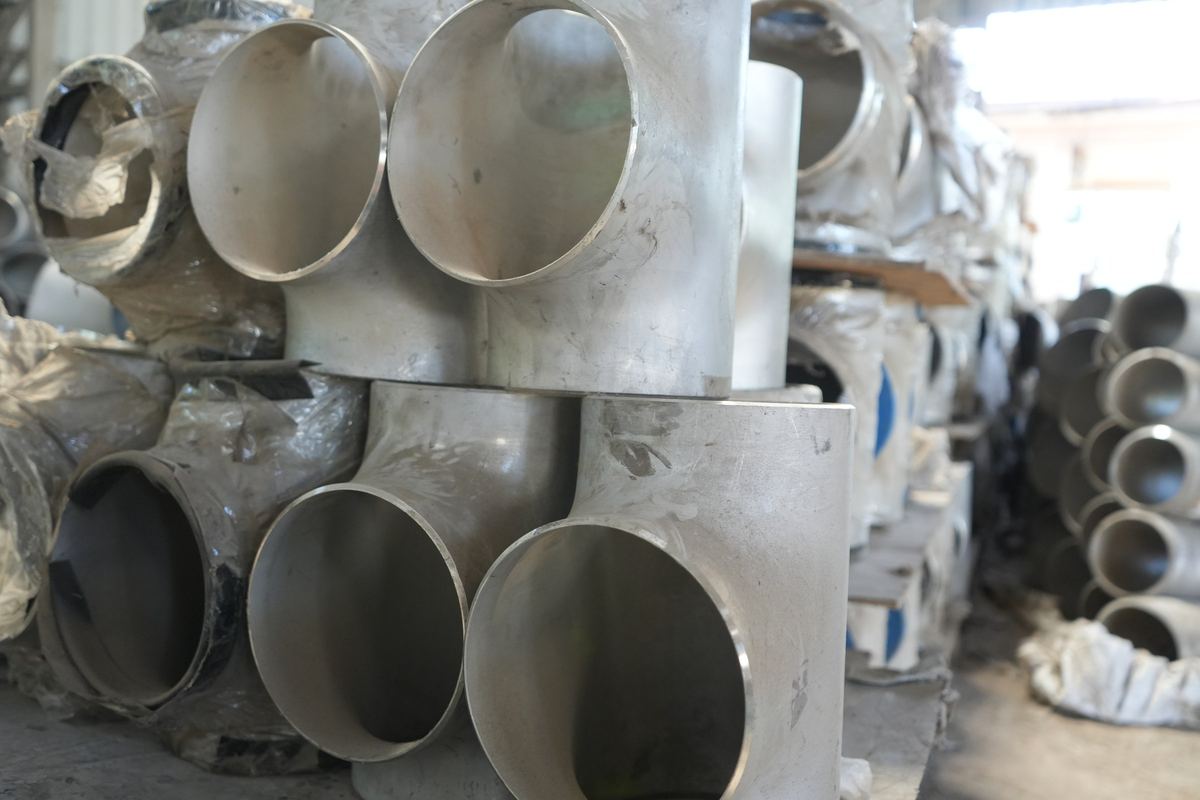
A secondary fluid network (SFN), also called the technology cooling system (TCS), is the closed loop that carries coolant from the CDU to the cold plates: distribution headers, row manifolds, in-rack manifolds, and the hoses and quick disconnects to each server. An efficient SFN is sized for the row's final heat load at about 1.5 L/min (0.4 gpm) per kW, runs at moderate velocity to keep pumping energy down, is balanced so every rack gets its flow, and is built clean in 304L or 316L stainless with butt welds and flanged breaks. We supply the 316L and 304L weld neck, lap joint and blind flanges for SFN headers, valves and CDU connections.
What a secondary fluid network includes
Vertiv describes the SFN as the layer between the CDU and the server racks. It has four levels, each with its own pipe size and joints.
| Level | Typical size | Material and joints |
|---|---|---|
| CDU, secondary side | 2.5 to 6 in connections on Vertiv's 600 to 2,300 kW CoolChip CDUs | Pumps, heat exchanger and 25 or 50 µm filters; sanitary or flanged connections |
| Distribution headers, CDU to rows | NPS 4 to 8 (DN100 to 200), larger on big galleries | 304L or 316L stainless, Sch 5S or 10S, butt welded, flanged at valves and module ends |
| Row manifolds | NPS 4 or 6 (DN100 or 150) | Stainless (304L with tri-clamp fittings in Vertiv's prefabricated manifolds) or polypropylene; overhead or under the floor |
| Rack branches and in-rack manifolds | NPS 1 or 2 (DN25 or 50) branches; vertical manifolds at the rear of each rack | Stainless, with hoses and dripless quick disconnects to each server |
Cold plate channels are about 100 microns wide, so every level is held to the same cleanliness rules. How the SFN relates to the facility loop is set out in FWS vs TCS, and the chip end in direct-to-chip liquid cooling.
Where an SFN gains or loses efficiency
Four things decide how much energy the network costs to run:
- Pumping energy. Friction loss rises with the square of velocity, so an undersized header costs pump energy every hour the hall runs. OCP favors lower velocities for efficiency, though high-performance systems may exceed 3 m/s (10 ft/s).
- Water temperature. Warmer water allows more hours of free cooling. Vertiv credits it for up to 70% better annual energy efficiency in its GB300 NVL72 reference design. Its CoolChip CDUs work at a 4 °C (7.2 °F) approach, so the TCS supply stays close to the facility water temperature.
- Balance. Racks that get too little flow are usually rescued by running the pumps harder.
- Cleanliness. Debris loads filters and fouls cold plates, and both add pressure drop.
Size headers for the final density
Vertiv's advice is to size headers for the highest row density you expect, not for the first racks: its example is a row moving from 100 kW racks to 200 to 300 kW. Branches should allow for upgrades too: 1.5 in rack connections today on headers that take ports up to 3 in, with pressure drop checked at full row utilization. OCP's 1.5 L/min (0.4 gpm) per kW turns the load into a flow; bore and velocity turn the flow into a size.
| Header | Bore | At 1.5 m/s (4.9 ft/s) | At 2.3 m/s (7.5 ft/s) |
|---|---|---|---|
| NPS 4 (DN100) | 108.2 mm (4.260 in) | 828 L/min (219 gpm), about 550 kW | 1,269 L/min (335 gpm), about 850 kW |
| NPS 6 (DN150) | 161.5 mm (6.357 in) | 1,843 L/min (487 gpm), about 1,230 kW | 2,826 L/min (747 gpm), about 1,880 kW |
| NPS 8 (DN200) | 211.6 mm (8.329 in) | 3,164 L/min (836 gpm), about 2,110 kW | 4,851 L/min (1,282 gpm), about 3,230 kW |
| NPS 10 (DN250) | 264.7 mm (10.420 in) | 4,952 L/min (1,308 gpm), about 3,300 kW | 7,592 L/min (2,006 gpm), about 5,060 kW |
The same arithmetic reproduces OCP's branch ratings: at 2.3 m/s (7.5 ft/s) an NPS 1 branch carries about 56 kW and an NPS 2 branch about 217 kW, against OCP's 55 kW and 170 to 220 kW. A 2,300 kW CDU, the largest in Vertiv's CoolChip range, needs an NPS 8 header to stay below 2 m/s (6.6 ft/s).
Velocity is where the efficiency is. Take a 1 MW row carrying 1,500 L/min (396 gpm) through 100 m (330 ft) of header:
| Header | Velocity | Head loss, m per 100 m (ft per 100 ft) | Pump power for that loss | Energy per year |
|---|---|---|---|---|
| NPS 4 | 2.72 m/s (8.9 ft/s) | 6.1 | about 2.3 kW | about 20,000 kWh |
| NPS 6 | 1.22 m/s (4.0 ft/s) | 0.8 | about 0.3 kW | about 2,700 kWh |
| NPS 8 | 0.71 m/s (2.3 ft/s) | 0.2 | about 0.1 kW | about 700 kWh |
Our calculation uses Darcy-Weisbach with the Colebrook friction factor, 0.045 mm roughness (conservative for new stainless), 65% pump and motor efficiency and year-round running. PG25 adds some loss, and fittings, valves, strainers and cold plates add more. One size up on a header costs steel and flanges once; the pump energy it saves recurs every year.
Lay out the network
- Route. Row manifolds run overhead or under the floor. Vertiv treats drip pans under row-level joints as best practice and detects leaks with moisture sensors and pressure differential.
- Isolation. Give every rack position supply and return isolation (Vertiv), and decide where module valves go: OCP compares valves at each module end with valves only at header ends.
- Growth. Leave blanked connection points on row manifolds for racks that will convert to liquid later, and pre-stubbed connections on the facility loop for future CDUs (Vertiv). On welded stainless headers those blanks are 316L blind flanges.
- CDU loading. Vertiv suggests starting CDUs at 60 to 70% utilization, not 90%, with N+1 planned for the expansion.
- Vents, drains and relief. Vent long runs and high points, but never put automatic air vents above IT equipment; fill and drain at the lowest points (Vertiv). ASHRAE TC 9.9's 2026 bulletin adds relief set below the IT equipment's maximum pressure.
Balance the flow
In a direct-return layout the racks nearest the CDU see the largest pressure difference and take more than their share of flow. Three tools even it out:
- Reverse-return headers, which give every rack a similar path length;
- Balancing valves or flow limiters on each row or rack branch;
- CDU control on differential pressure or flow, both offered on Vertiv's CoolChip CDUs.
Whatever the method, balance is proved rack by rack in functional testing; at CLDC Mumbai 01, Vertiv used what it calls SFN-Tab kits after commissioning.
Materials and joints
OCP's modular TCS paper reviews each joint type used in these loops:
| Joint | What OCP says | Where it fits |
|---|---|---|
| Butt weld | To ASME B31.3 and AWS D10.18; passivate after welding or hot work | The default along headers and row manifolds |
| Flanged | Needs good alignment and bolt torque checks | Valves, strainers, filters, CDU transitions, module ends and future branches |
| Grooved | Reliable with visual verification; gaskets compatible with PG25 and rated for vacuum | Facility side and some TCS headers (grooved vs flanged) |
| Tri-clamp (DIN 32676) | Hygienic; inspect and retighten periodically | Prefabricated row manifolds and many CDU connections |
| Threaded | BSPP if needed; field use discouraged; no tape or pipe dope in the TCS | Instrument and vent points only |
For the material, OCP notes that stainless 304 or 316 is widely used, that chloride should stay below 25 ppm where 304 is chosen, and that carbon steel is avoided because it adds corrosion products. Vertiv's TCS guidelines prefer 304L or 316L and recommend peroxide-cured EPDM for elastomers.
For the flanged breaks, specify:
- ASTM A182 F316L or F304L forgings to ASME B16.5 Class 150 or EN 1092-1 PN16;
- weld neck bored to the pipe schedule, or a lap joint flange with stub end where bolt holes must line up with a valve;
- pickled and passivated to ASTM A380 and A967, with 100% PMI and an EN 10204 3.1 certificate.
Keep slip-on flanges out of the SFN: their internal fillet weld leaves a crevice. More on our TCS flanges page.
Build it clean
- Shop modules. OCP's modular approach has modules cleaned to ASTM A380, passivated, pressure tested at 1.3 to 1.5 times the design working pressure, drained, dried and purged with dry nitrogen. They stay sealed with tamper-evident caps until installation.
- Dust on site. Vertiv's TCS guidelines say not to install piping while dust is in the air, to cap every opening during assembly, storage and transport, and to stop dusty trades such as drywall work during fill. OCP's working group is drafting a pre-commissioning standard it calls "Dusty but not Dirty".
- Flushing. Flush, filter and fill before any server is connected: steps and targets in TCS flushing and cleaning.
Test and commission in levels
Commissioning runs in five levels, and an SFN passes through all of them:
| Level | What it covers | For the SFN |
|---|---|---|
| L1, factory acceptance | Equipment tested at the maker before shipment | CDU factory tests; module pressure test before shipping |
| L2, site acceptance | Delivery checked against the factory-tested build; installation basics verified | Caps intact, materials and certificates checked against the drawings |
| L3, pre-functional | Each device checked in isolation | Hydrotest, flush, fill and vent; valves, sensors and leak detection checked |
| L4, functional | Whole systems tested under controlled conditions | CDUs and SFN at design flow and heat load; balance verified rack by rack |
| L5, integrated systems test | The whole facility tested together, including a utility power loss | Pumps, CDUs and controls ride through the failure with the rest of the plant |
An SFN in practice: CLDC Mumbai 01
In October 2026 Vertiv announced the SFN for CapitaLand India Trust's CLDC Mumbai 01 data center in Airoli, Navi Mumbai, which it calls India's first direct-to-chip high-density liquid cooling deployment. The closed loop runs from the facility's cooling plant to chip level and supports 30 MW of AI workloads for a hyperscale customer. The release names four practices worth copying:
- customized technology loop skids, which Vertiv now builds in a dedicated production facility;
- SFN-Tab kits to balance the technology loop after commissioning;
- installation and commissioning procedures, developed with CapitaLand Investment, to keep dust out of the loop;
- comprehensive Level 4 testing on site before go-live.
For the flange specification that suits Mumbai's coastal climate, see our Mumbai data center page.
Frequently asked questions
Is the secondary fluid network the same as the technology cooling system?
Yes. Secondary fluid network (SFN) is the term Vertiv and some other suppliers use; technology cooling system (TCS) is the ASHRAE and Open Compute Project term. Both mean the closed loop between the CDU and the cold plates.
What size are SFN headers?
Row manifolds are typically NPS 4 or 6 (DN100 or 150), and distribution headers on large galleries go to NPS 8 and up. Size them for the row's final load at about 1.5 L/min per kW: an NPS 6 Sch 10S header carries roughly 1.2 to 1.9 MW at 1.5 to 2.3 m/s.
Should SFN piping be stainless steel or polypropylene?
Vertiv lists both for row manifolds, and OCP discusses PPR, CPVC and HDPE mainly for door heat exchanger loops. For direct-to-chip loops stainless 304 or 316 is the usual choice: it can be welded, passivated and pressure tested like process pipe.
How is a secondary fluid network balanced?
With reverse-return headers, balancing valves or flow limiters on branches, and CDU control on differential pressure or flow, checked rack by rack in L4 testing.
What pressure class do SFN flanges need?
ASME B16.5 Class 150 or EN 1092-1 PN16 is ample. OCP gives a maximum operating pressure of 4 bar (60 psi) for liquid-to-chip loops, while a Class 150 flange in 316L is rated 15.9 bar (230 psi) at ambient temperature. The class is chosen to match valves and CDUs.
Sources
- Vertiv, Understanding fluid networks in liquid-cooled data centers: a complete guide, 10 March 2026 (layers of the network, header sizes and materials)
- Vertiv, Row-based manifolds: the backbone of liquid cooling in modern data centers, 1 December 2025 (304L tri-clamp manifolds, leak monitoring)
- Vertiv, Designing liquid cooling infrastructure for scalability: best practices for future growth, 11 May 2026 (header and branch sizing, CDU utilization, isolation, blanked connections)
- Vertiv, Guidelines for Deployment of Single Phase Technology Cooling System, SL-80056 Rev A, February 2025 (materials, elastomers, vents and drains, dust control)
- Vertiv, CoolChip CDU 600, 1350 and 2300 kW data sheet, SL-80005, May 2026 (approach, filtration, connections, control modes)
- Vertiv, news release on its reference architecture for the NVIDIA GB300 NVL72, 11 June 2025 (warmer water and energy efficiency)
- Vertiv, news release on the CLDC Mumbai 01 deployment for CapitaLand India Trust, 16 October 2026
- Open Compute Project, Modular Technology Cooling System for "Cloud Scale": Design and Delivery of Liquid to Rack Distribution Systems, version 1.0, 25 August 2025 (flow per kW, velocities, branch ratings, joints, materials, module preparation)
- Open Compute Project, Technology Cooling System Pipe Distribution sub-project page (read 28 October 2026), for the "Dusty but not Dirty" pre-commissioning work
- ASHRAE TC 9.9, TCS Coolant Integrity and System Readiness Best Practices, May 2026, as summarized by StorageReview, 30 August 2026 (vents and relief)
- ASME B16.5-2020, Pipe Flanges and Flanged Fittings, Table 2-2.3 (Class 150 rating of 304L and 316L)
- Archdesk, Data center commissioning levels, 26 June 2026 (L1 to L5)
- ASME B36.19M, Stainless Steel Pipe (Sch 10S bores); RIC calculation of capacities and friction losses as stated under the tables